

Resistance Spot Welding, just like all of the other solid-state processes, relies on the inherent bulk resistivity of a material as its means of generating heat when a current is passed through it. This physical phenomenon is described by Joule’s first law (also known as the Joule-Lenz law) which states the heat (Q) generated by an electrical conductor is equal to the current (I) multiplied by the voltage (V) and the time (t) the current is allowed to flow, or Q = IVt. Ohm’s Law states that Voltage (V) is equal to current (I) multiplied by resistance (R), or V = IR. This means Joule’s Law can also be written (after a substitution) as Q = I2Rt.
In other words, the amount of heat going into the weld is equal to the square of the current multiplied by the resistance and the time current is flowing through the weld. A side note: This equation assumes the electrical resistance and current are constant, which is not always the case with resistance welding.
To help further our understanding of resistive heating (and subsequently resistive welding), it might be helpful to see how some materials relate to others with respect to their bulk resistivity. For purposes of this conversation, we will limit things to just a few materials common in our lives. Finally, resistivity is symbolized by the Greek letter ‘rho’ (ρ), and has units of ‘ohm meter’ (Ω•m). See Table-1 below for a few examples.
Table-1: Material Bulk Resistivity
| Material | Resistivity (ρ) Ω•m* | Comments |
|---|---|---|
| Silver | 1.59 x 10⁻⁸ | |
| Copper | 1.68 x 10⁻⁸ | |
| Aluminium | 2.82 x 10⁻⁸ | About 1/3 of Iron |
| Nickel | 6.99 x 10⁻⁸ | |
| Iron | 10.1 x 10⁻⁸ | About 3x that of Aluminum |
| Nichrome | 110 x 10-8 | Element for an electric range |
* A bit of literary license was used with the scientific notation to keep the same exponent, making comparisons a bit easier.
As seen above, there can be a great deal of difference between the bulk resistivity of materials we deal with in our everyday lives. A few quick observations:
- Copper has a very low value for bulk resistivity. This means it is a good conductor. It is this low bulk resistivity that allows us to weld both aluminum and iron alloys with electrodes made from copper, without themselves being welded to the part (well, in most cases…).
- The bulk resistivity difference between aluminum and iron is significant (about a factor of 3). However, it is not so much that we cannot relate one to the other. Sort of like talking to someone from the UK – A common language with a few differences.
So how does the aforementioned information help us utilize the RSW process to join the various aluminum alloys, or any other material for that matter? A part of the answer lies in the amount of heat the material generates when current is passed through it, and this is where bulk resistivity comes into play. We mentioned earlier the total heat into a weld can be expressed as Q = I2Rt. With this in mind, it makes sense when comparing aluminum to iron we will need either more current or weld time to make up for the difference in total heat reduction due to this loss of resistance. However, as is often the case, we cannot focus on only one material property, in this case bulk resistivity, when determining the best way to make a resistance spot weld.
To help further our understanding of how we are going to join aluminum by means of resistance spot welding, we need to consider two other fundamental material properties. These would be aluminum’s melting point and plastic range, and how both of these relate to iron. The specifics are in Table-2 below:
Table-2: Material Properties - Steel vs. Aluminum
| Material Property | Aluminum | Iron |
|---|---|---|
| Melting Point | 660 ⁰C | 1538 ⁰C |
| Plastic Range | ~93 ⁰C | ~538 ⁰C |
As can be seen above, there is a great deal of difference. Specifically, the melting point for aluminum is much lower, and the plastic range much narrower. So, what does this mean?
For starters, this means the amount of heat required to generate fusion temperatures for an equivalent volume of aluminum is actually lower than iron. However, due to the lower melting point, aluminum reaches its plastic range at a much lower temperature than iron. This can make maintaining sufficient plastic material to constrain the molten nugget more difficult with aluminum alloys. Translation: The actual process window available to create an acceptable spot weld in aluminum will be smaller than iron in that we have a narrower permissible variation in both current and weld time to work with.
We now know our challenge. To successfully use the RSW process to join aluminum, we must account for its lower (in relation to iron) bulk resistivity, melting point, and plastic range. To help bring all of the above together, the following rule of thumb might be helpful. Like all rules of thumb, they can get you in the right area code, maybe even the proper zip code. However, a bit of finesse will be required to get to the correct address (or weld schedule).
There are many standardized weld schedules available for the RSW process, and they come in many forms (See Ref-1 & Ref-2). With the aforementioned in mind, is it possible to relate the information contained in a steel weld schedule chart to one for aluminum? And more importantly, see how the welding industry has accounted for the differences between these two materials? The short answer is a qualified yes. While not exact, a review of both a steel (think uncoated HSLA) and aluminum welding chart should yield the following rough approximations. I call them the Rules of 3-1-1/3.
- This higher current requirement accounts for both the lack of bulk resistivity present in aluminum required to generate the needed heat for melting, and the heat drawn out of the weld by the surrounding material.
- One place where this rule breaks down is if the surface of the aluminum has been freshly cleaned (think some aerospace applications). In these instances, it is not uncommon for the required secondary current to be 4x (or more) than one would see in steel.
- A certain amount of unaffected base material must be present to surround the newly forming weld nugget, and while dependent on many factors, aluminum and steel like roughly the same weld force.
- For purposes of this discussion, we are not talking about the forging force that many aluminums (think the heat treatable series) can benefit from while being joined by the RSW process. That is a whole other subject, but suffice to say the forging force will be much higher (at least >50%)
- Here is where the narrow plastic range really comes into play. This narrowness means the process window for aluminum is smaller. As a result, one must use a lower, and very targeted, value for weld time.
- A way to address the need for this more exact (or targeted) weld time is to ensure one is utilizing the weld schedule charts in a way that allows for this. To be more specific, this means if the governing gauge of the aluminum RSW weld in question has a value between two different lines on the weld schedule chart, it would be advised to determine, by means of interpolation, ratios, or a mid-point calculation, a more exact value of weld time for the gauge in question.
Now that we have a feel for how to make a resistance spot weld in aluminum, the next step is understanding the fact that not all aluminums are created equal. Whatever the alloy, or its post processing regimen, the full callout should detail the information needed.
Once it has been determined what type of aluminum alloy is being dealt with, the next step is to utilize this information and consult a compatibility chart to see the best way to proceed forward. These charts are available from a variety of sources, including the AWS C1.1, or the RWMA manual. Whatever their source, in the end, they try to establish four (4) basic things:
- The ease of welding the combination in question. This category is often ranked into degrees of difficulty, and can even go so far as to include a recommendation not to weld the materials in question together.
- The pre-cleaning requirements. This can range from not required (very rare) to the surface requiring a chemical and/or mechanical cleaning in order to make a weld. Of note, I have not seen how the surface pre-treatments now available in the marketplace are included in these charts. If your material has such a coating, a consultation with the manufacturer might be beneficial.
- The resistance to corrosion of the resultant weld metal. Specially, it is either as good as the parent metal or not.
- An acknowledgment that the chart is incomplete. Just as with the surface pre-treatments, the base material world is ever evolving so you may be reaching out to the manufacturer to see what the compatibility is with their material.
Once the compatibility issue has been addressed, it is now down to an execution of the fundamentals of RSW to make the weld. If one utilizes properly sized equipment, to include a capable power supply, with the correct electrode caps, on properly designed parts you almost can’t help but have a cost effective and robust process. This is why despite all of the other wonderful methods of joining metallic materials together, resistance spot welding is not going away any time soon.
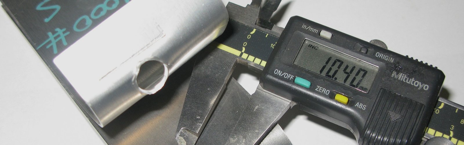
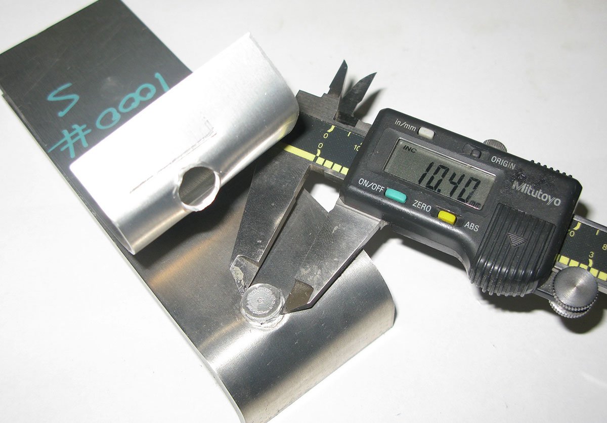
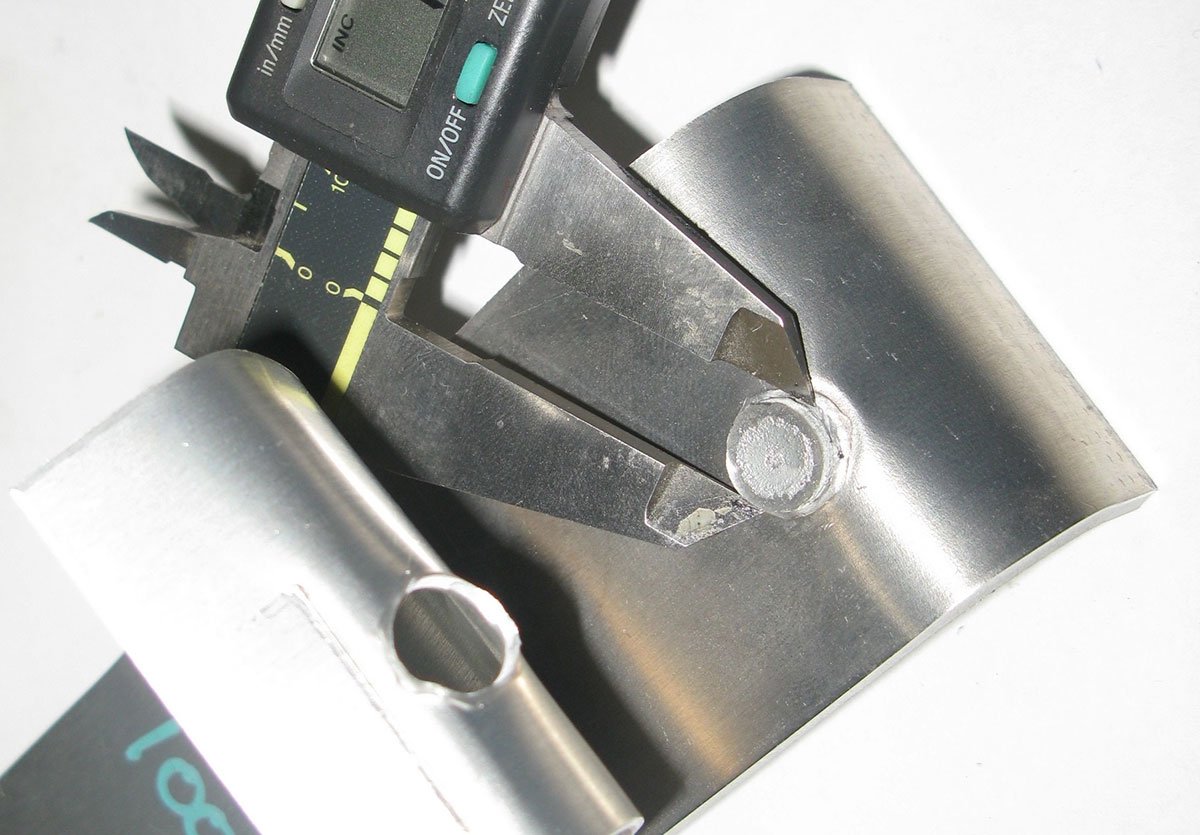
Figure-1: Photo of a peeled aluminum spot weld. The measurement displayed is accurate as the required MWS (minimum weld size) for this application was rather large relative to the material gauge.
References:
1) Resistance Welding Manual, revised 4th Edition
2) AWS C1.1M/C1.1:2019, Recommended Practices for Resistance Welding
Donald F. Maatz, Jr. is with Milco Manufacturing, and serves in the capacity of Senior Welding Engineer. He is past-chairman of the AWS-Detroit Section, serves on the D8 and D8.9 Automotive Welding Committees, is chair of the D8D, and an advisor to the C1 Resistance Welding Committee, is an AWS endorsed CWI and an instructor for the RWMA School. He is a graduate of Ohio State with a BS in Welding Engineering. This article would not have been possible were it not for the assistance from members of the Milco team. Send your comments/questions to Don at dmaatz@milcomfg.com