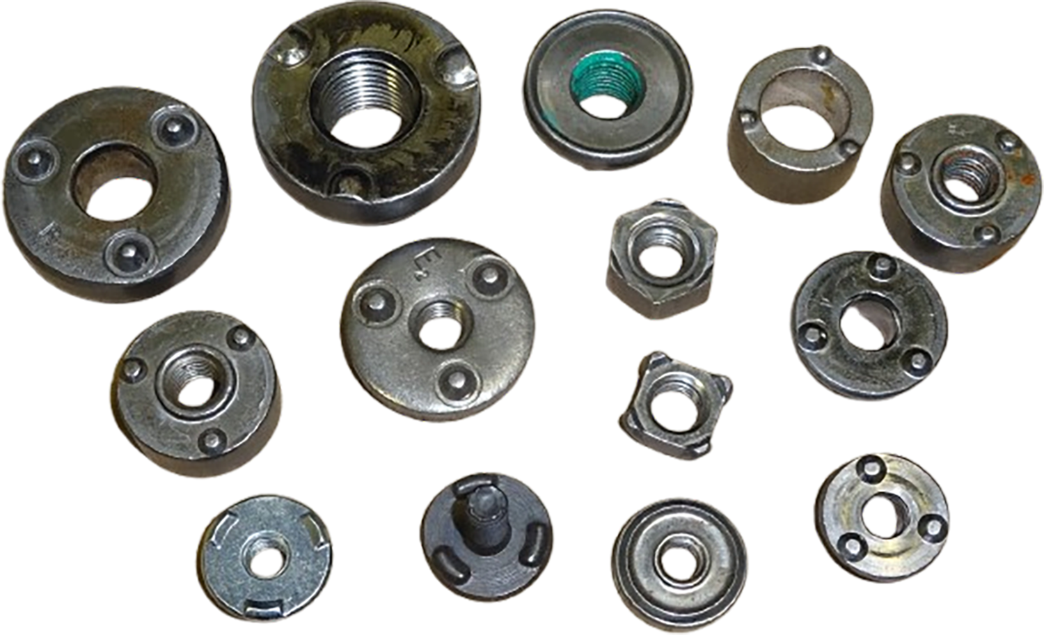
The purpose of this column is to take a look at a different aspect of the projection welding (PW) quality criteria, and it may be one that flies under most folks’ radar. For clarity, when we are talking about PW, we are talking about the welding of forged/coined weld nuts, not their hollow, embossed brethren.
As an aside, there are valid reasons we are not nearly as concerned about embossed or hollow projections and how they are welded or evaluated. Why? There are entire books dedicated to the subject. With the large volume of material available, I would be adding nothing new to the embossed PW conversation. One glance at just Ref-1 and Ref-2 reveals just about everything one needs to know on the matter. And I am not kidding; in addition to very excellent schedules, they even have prints on how to make the punches and dies. An absolute ton of great work captured by those before me, and my hat is off to them – well done! But getting back to the matter at hand…
The main driver for almost all of the PW weld schedule strategies in use today is the need to achieve the required destructive push-off force. It is the number folks focus on, and it goes without saying, is very important. However, I think there is an important, albeit secondary, element at work within the PW community further driving the need (or perception thereof) for how the weld schedule is determined, and from my perspective, it should be addressed – Weld Nut Set-Down.
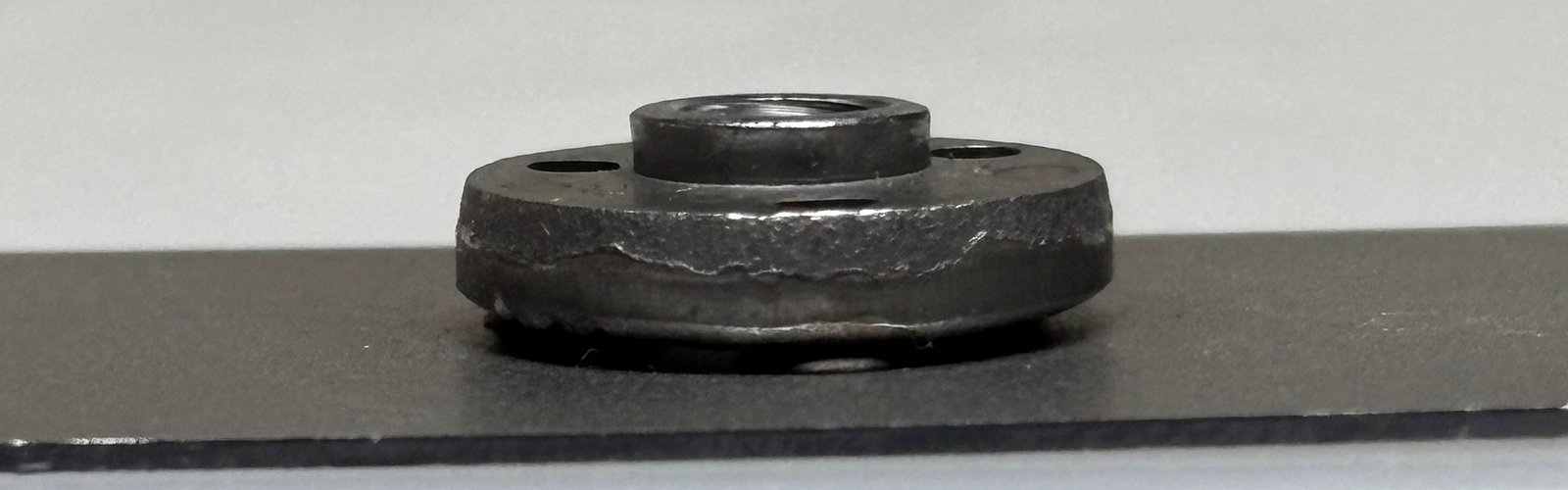
Set-Down is based on the measurable distance between the base metal and part containing the projection after completion of the welding sequence. And I might be getting just a bit ahead of myself, but it has almost ZERO relation to the strength of the final welded assembly. However, this does not stop folks from getting just a bit hung-up over the concept. More about that later.
To take things a step further, it might be beneficial to understand a bit more about Set-Down, and more importantly, how the industry views this specific acceptance criteria. As one can imagine, there are many acceptability standards associated with the PW process, and each offers their perspective on what is, and is not, acceptable. And Set-Down falls squarely into this category.
For completeness, cross-wire welding is also technically a projection weld. One nuanced difference between cross-wire and either an embossed (hollow) or forged/coined (solid) projection weld is that while the Set-Down of a cross-wire weld is also measured after it has been made, it is in reality a Depth of Penetration (DoP) determination. I say this as, once welded, a cross-wire weld has, by definition, zero gap since the parts are the projections. With this in mind, we will focus on solid projection welds (to include a full-ring) for the remainder of this discussion on Set-Down.
When discussing Set-Down, one also needs to acknowledge (I think), the idea of parallelism. Even if welding an assembly with just a single projection, there are part mating surfaces that need to be ‘square’ to each other. The concept of ‘squareness’ is always going to be application specific, but I think for purposes of this discussion is good to consider.
The measurable criterion known as Set-Down is viewed very differently by those from within the industry. To further amplify, some standards state a specified (really a target) value whereby a PW made with a Set-Down in violation of the limits is not discrepant. Other standards specifically state that a lack of adherence to the Set-Down requirements is a discrepancy.
To help provide a feel for the varied differences, we will take a look at the requirements of several different standards as they apply to PW and the measurable criteria known as Set-Down and Parallelism. The following items are paraphrased a bit, but capture the needed detail.
…shall be set down so that the gap between the base of the fastener and the mating part is no more than 0.3 mm or 30% of the pre-weld projection height (whichever is lesser) and is not a criterion for welds to be discrepant…
…side-to-side gap shall not differ by more than 0.2 mm, but is not a criterion for welds to be discrepant…
…discrepant if the maximum gap is >0.1 mm, with a target value is 0.00 mm…
…discrepant if more than five degrees off perpendicular…
…discrepant if the gap between the welded parts exceeds 20% of the original projection height…
…parallelism of the welding projections of max. 0.1 mm relative to the contacting surface…
As can be seen from the above snippets of information, no one agrees with anyone. The values are either percentages of projection heights, or hard values, or both. Some consider anything in excess of the stated values to be cause for a weld discrepancy, while others do not. Some address both Set-Down and Parallelism, while others address only one of them. Frankly, this level of inconsistency with regard to a single measurable characteristic is rare in the welding industry. And as I alluded to earlier, almost none of this relates in any way to the push-off strength of the final assembly.
The possible reasons for these differences are varied. However, I think they can be boiled down to a few broad categories.
- In-Process vs. Structural: Are the projection welds in question strictly manufacturing welds, or are they needed to carry an actual load? An example of a manufacturing application might be a weld nut that has a subsequent bolt assembly process that might be important (think a door hinge), but once torque is achieved and everything is sandwiched together, the welds on the actual nut could instantly disappear and there would be no loss of functionality. It is fully acknowledged any eventual repair of the product may be more difficult, but the part as assembled will be fine.
- Type of Loading: The vast majority (but not all) of PW applications have the load applied to the part in a compressive nature. It does not take much imagination to visualize the various OEMs processing their PW applications in differing manners (think applied loads in tension or shear), each with their own level of acceptability requirements.
- Assembly Issues: In some cases, the design can be so tight that excessive (or even moderate) measured gaps might result in part fit-up issues. This can be seen in areas where many items are coming together in a confined space. As an example, an automotive B-pillar.
- Issues in Paint: While less common, it is possible for the space between the welded parts to act as a fluid trap. The vast majority of weld nuts are located in areas where this not an issue. However, in those cases where any kind of redeposit can occur, you can bet the chorus requesting a ‘Zero’ Set-Down weld will be loud, and persuasive.
So, what is my issue with Set-Down and how the industry views it? To be a bit more specific, it is not uncommon to see folks conflate Set-Down with push-off strength. By this, I mean they think it is not possible to have a good push-off value unless you have good Set-Down (meaning zero to minimal gap). And they then think the opposite must also be true – If I have good Set-Down, I must then have good push-off values. Not to be the bearer of bad news, but both points of view can be very wrong. In fact, if all that was needed for a good PW was Set-Down, then a ‘long weld time’ weld schedule approach would be the norm with the PW process, and not the much less than optimal exception.
It should be noted a proper PW does require some significant degree of set-down. This is due to the projections serving as a concentration point for both force and current (very similar to Resistance Spot Welding (RSW) electrode caps). As the welding current and force passes through the projections, it causes a highly localized heat path to form. This, in turn, causes the metal at the projection to rise quickly to a plastic temperature, after which it is flattened and (if all goes well) forms a bond between the weld nut and the part.
Will all that being said, it is still possible to have mismatches between projections and the base material. These issues are due to varying base metal gauges, projection geometries, material coatings and strengths. And when these issues are severe enough, it is actually fairly easy to achieve a great value for Set-Down, and a very poor value for push-off force.
With the aforementioned very much in mind, my experience with regard to Set-Down is to (providing you have good push-off) keep the value to something <25% of the projection height, and hold parallelism as tight as possible. As long as all other quality aspects are acceptable, this should work fine.
References:
1) Resistance Welding Manual, revised 4th Edition
2) AWS C1.1M/C1.1:2019, Recommended Practices for Resistance Welding
Donald F. Maatz, Jr. is with Milco Manufacturing, and serves in the capacity of Senior Welding Engineer. He is past-chairman of the AWS-Detroit Section, serves on the D8 and D8.9 Automotive Welding Committees, is chair of the D8D, and an advisor to the C1 Resistance Welding Committee, is an AWS endorsed CWI and an instructor for the RWMA School. He is a graduate of Ohio State with a BS in Welding Engineering. This article would not have been possible were it not for the assistance from members of the Milco team. Send your comments/questions to Don at dmaatz@milcomfg.com.