



What is a weld schedule? For a generic definition of what a weld schedule is we can turn to the AWS A3.0 (Standard Welding Terms and Definitions). If we look at the 2025 version of this excellent document we can find the following definition for welding schedule: A written description, usually in tabular form, of welding procedure variables and sequence for performing a welding operation for a specific application.
When one considers a definition such as this must cover every welding process, it is not bad. However, since we are talking specifically about Resistance Spot Welding (RSW), we both need and want to get a bit more specific. But how specific? Let’s start by taking a look at some of the required elements in an RSW schedule, and see how deep we need to go.
For some historical context, I have had more than one person say to me they did not understand why RSW was so complicated. When I asked why they would think something like that, I received a version of “force, current and time – how hard can it be?” I guess to a point, that is fair – the industry does drive home those three (3) critical elements of a RSW schedule. All. The. Time. Of course, one can say the same thing about a driver in the Indianapolis 500. All they do is control the steering wheel, pedals, and gear shift – again, how hard can it be? It goes without saying both of these analogies are just a bit over-simplified. However, in the case of RSW, those three (3) critical elements are also an excellent place to start as we go about creating a weld schedule. But before we go any further, let’s take a moment and see what the industry has already provided. To do this we will start with something called the standardized weld schedule or weld chart.
It starts as a simple recipe
From my perspective, a standardized RSW schedule is the generic outline detailing the bare essentials needed to create a weld (see Figure-1). To build on this basic understanding, it is important to keep a few things in mind when reviewing any standardized RSW schedule. To help with this, we will use the AWS C1.1 (Recommended Practices for Resistance Welding) as a guide.
The AWS C1.1M/C1.1:2019 contains 44 standardized weld schedules for varying processes and materials, and one is really a RSW gauge ratio chart. Of the 44 standardized schedules, 26 are for RSW. The balance of the remaining weld schedule charts are for (in frequency of appearance) resistance seam welding (RSEW), embossed projection welding (PW), and flash welding (FW).
All of the aforementioned schedules share many things in common. To summarize a few of them:
- The schedules are material specific. A quick glance at the C1.1 table of contents reveals not only obvious differences in the substrate of each schedule (think aluminum, nickel-based alloys or steel), but also subsets of each material type based on several characteristics, to include its coating and/or strength, or series of aluminum.
- The methodology of each process can be specified: This would include, as an example, whether or not the schedule is based on a pulsed or single application of weld time.
- The standardized schedules typically only specify main parameters: In the case of RSW, this would mean (please repeat after me); electrode force, secondary weld current, and weld time. Other elements of a schedule not typically addressed would include Squeeze Time, Hold/Cool Time, Up and/or Down Slopes, Pre & Post Heats, and many others. It should be noted, there are schedules in the C1.1 that detail some of these specific elements, as an example the 6000-series aluminum schedule specifies both Up and/or Down Slope, and a recommended forging force.
- Electrode geometry may or may not be specified: The AWS C1.1 does an excellent job of indicating the electrode geometry on which the weld schedule is based. However, some standardized charts do not list this very important piece of information. The main reason for this omission is the schedule may be a part of a larger standard, and the electrode geometry is specified in some other portion of the document. This is often the case with the automotive OEM standards.
- They are essentially design schedules first, and welding schedules second. What do I mean by this? For starters, while the stated forces and weld times are appropriate, the weld currents are typically a bit higher than is needed to make a successful weld. And this is not a bad thing. From a tooling perspective, one can utilize the listed current, force and weld time, add a safety factor (think 20%) for both structural and thermal sizing, and end up with robust, capable equipment. Once on the floor, all one needs to do is program in the listed schedule, dial the current back to something a bit less than what is specified, and start making welds. When one becomes more familiar with how a specific chart reacts to an application, the ‘first hit’ becomes more refined. On a personal note: I have one default chart I use for all steel RSW, and over time have learned I can often get very close to something workable right out of the gate by utilizing minor adjustments to this information.
What do we need?
As was alluded to above, several factors need to be considered in order to utilize a standardized RSW schedule. First and foremost, we need to know enough about our process to select the applicable standardized schedule. And this may entail just a bit more than meets the eye. Why do I say this? The primary reason is that, despite our best intentions, we live and work in a complex world. And that means the welding we need to perform will very likely not be of the ‘plain vanilla’ sort.
To be more specific, the process of selecting the applicable standardized schedule may require you to answer more than a few questions. To elaborate on this point, one may need the following: The type, gauge & coating of each material to be welded, the equipment being utilized, and the quality requirements associated with the weld(s) in question immediately come to mind.
- Material – There can be significant differences in how one approaches the joining of different materials together using RSW. We detailed some of these in our comparison of steel and aluminum (see ‘Aluminum Welding Schedules’ under the Milco Educational Resources page [https://www.milcogroup.com/educational-resources]). However, the RSW process can also be used to weld stainless steel, and other alloys including, but not limited to, Nickel (Ni), Copper (Cu), Chromium (Cr), Iron (Fe) and Titanium (Ti). It goes without saying that each unique combination has its own idiosyncrasies. However, that is exactly why the standardized schedule can be so beneficial. In so much as possible, the industry has come together to assist us with making a robust resistance spot weld – we would be wise to listen.
- Stack-Up Ratio – It should come as no surprise that we are not often asked to use the RSW process to weld a material to itself. In other words, practicality every weld made with the RSW process is, in one form or another, asymmetric in nature. To that end, we need to know how the schedule should be used not only when common materials of differing gauges are to be joined, but what we should do if there is a disparity between the properties of the materials. Think of the potential strength and gauge differential between a very strong and thick seat belt reinforcement bracket, and the thinner bare mild steel B-Pillar inner to which it is welded. In this example, both materials are ‘steel’, but that is about where the similarity ends. Our welding process has to deal with differences in substrate gauge, strength, and coating. And once again, standardized schedules can help point us in the right direction.
- Welding Equipment – While it is understood that many of the standard schedules do not differentiate between the AC and MFDC RSW process, the standardized schedules can be tailored to other specific equipment and processes. Again, both the AWS C1.1 and RWMA Manual are helpful in this regard, as a quick glance at the table of contents reveals possible RSW schedules for three-phase frequency converter machines, among others.
- Weld Quality – This is really a question about the desired size, and perhaps the subsequent strength, of the material where we desire a weld. There can be applications requiring a larger minimum weld size (MWS) than others. When these situations arise, one needs to understand the relationship between the electrode caps associated with the schedule in question, and the weld size that can be achieved with them. This is one area where a few extra words might be beneficial: One must be aware that the electrode contact face is neither over- or under-matched for the application, as either condition will result in a less than robust process.
- Other Factors – Not all schedules can accommodate all circumstances. These special cases might include the presence of a structural adhesive or sealer (pumpable or tape), single-side coated materials, or limited mixed materials (stainless steel to a coated HSLA, anyone). To that end, each of the elements above may have further accompanying design guidance available to assist with the situation. The most common instances of this would be Gauge Ratio and Material Strength charts.
So, what does all this mean? For a standardized schedule to be beneficial to the user, its structure must be thoroughly understood. This means taking the time to review all of the various footnotes and special details associated with the standardized schedule in question. As there is no real set format, the information one may need is not going to be in a set location. However, my guess is that it will be there.
Let’s get specific…
It might be best if we looked at a specific application – an example of what one needs to do in order to create a design weld schedule. And as mentioned above, the end result will have the key elements of force, current, and time. However, those are the end product of our efforts, not the start.
The following is a methodology (there are others) one can use to create a RSW weld schedule. Right out of the gate, one MUST know more than a few things in order to create an RSW welding schedule. Now, there are a few of these areas where it is possible to make an educated assumption to fill in the blanks until more accurate information is available – with the understanding that where and when one can make assumptions will vary by application. Regardless, in all cases, it would be most beneficial to be very clear and list on what basis all weld schedules are created. As an aside, I have seen dedicated forms used to document this process, and they can be very beneficial.
It should come as no surprise that not everyone agrees on what type of RSW they need for a given application. And dependent on which standardized weld schedule chart one uses, the answers will vary, somewhat. The amount of variation from one chart to the next can run the gambit from subtle to significant. How? Again, dependent on the application, one chart may specify a single-pulse, while another may want a multi-pulse weld time. Either way can work, with the user needing to make the final determination. One final thought on this subject: While the varying design standards may provide differing methodologies to determine a weld schedule, the truth of the matter is the vast majority of welding quality standards are written to evaluate the end-result – the weld itself, and not the style by which it was made.
To help illustrate these application specific concepts we will use two (2) common weld charts from the AWS C1.1M/C1.1:2019, plus the gauge ratio chart.
- Table 1: Spot-Welding Parameters for Bare, Galvanneal, and Galvanized Low-Carbon Steel <350 MPa [72 ksi] Ultimate Tensile Strength
- Table 4: Spot-Welding Parameters for Bare, Galvanneal, and Galvanized Low-Carbon Steel 350–700 MPa [50–108 ksi] Ultimate Tensile Strength
- Table 36: Spot-Welding Parameters for Various Thickness Combinations and Arrangements of Uncoated and Coated-Carbon and Low-Alloy Steels
We will also use four (4) separate stack-ups so one can see how the different elements interact.
- 89 mm HDG MILD CR3 / 0.89 mm HDG MILD CR3
- 89 mm HDG MILD CR3 / 1.40 mm HDG MILD CR3
- 89 mm HDG HSLA550 / 1.40 mm HDG MILD CR3
- 89 mm HDG HSLA550 / 1.40 mm HDG MILD CR3 / 1.40 mm HDG HSLA550
The information in Table 36 further amplifies the selection of the GMT for a given stack-up. In this case, the table details the ten (10) possible ways various metal gauge combinations can be combined, either as a 2T or a 3T, and the GMT for each. It then details the ratio limitation for each separate stack-up, and suggested weld schedule adjustments for both weld force and current only. Finally, and this is unique within the RW industry, the table does this for three (3) electrode geometry combinations.
A quick glance at either weld schedule chart (Table 1 or Table 4) will reveal a host of information related to many of the items already mentioned earlier in this article. A less than complete list of the available welding related elements associated with each table, and its footnotes, would include:
- The applicable electrode caps, with the required adjustments for specific geometries
- Guidance with regard to metal gauge selection, or by its more formal term: Governing Metal Thickness (GMT)
- Recommended weld force, current and weld time for discrete material gauges
- Weld size & strength requirements, based on the above gauge information
- Any recommended adjustments for welding with either AC or MFDC
Create a weld schedule
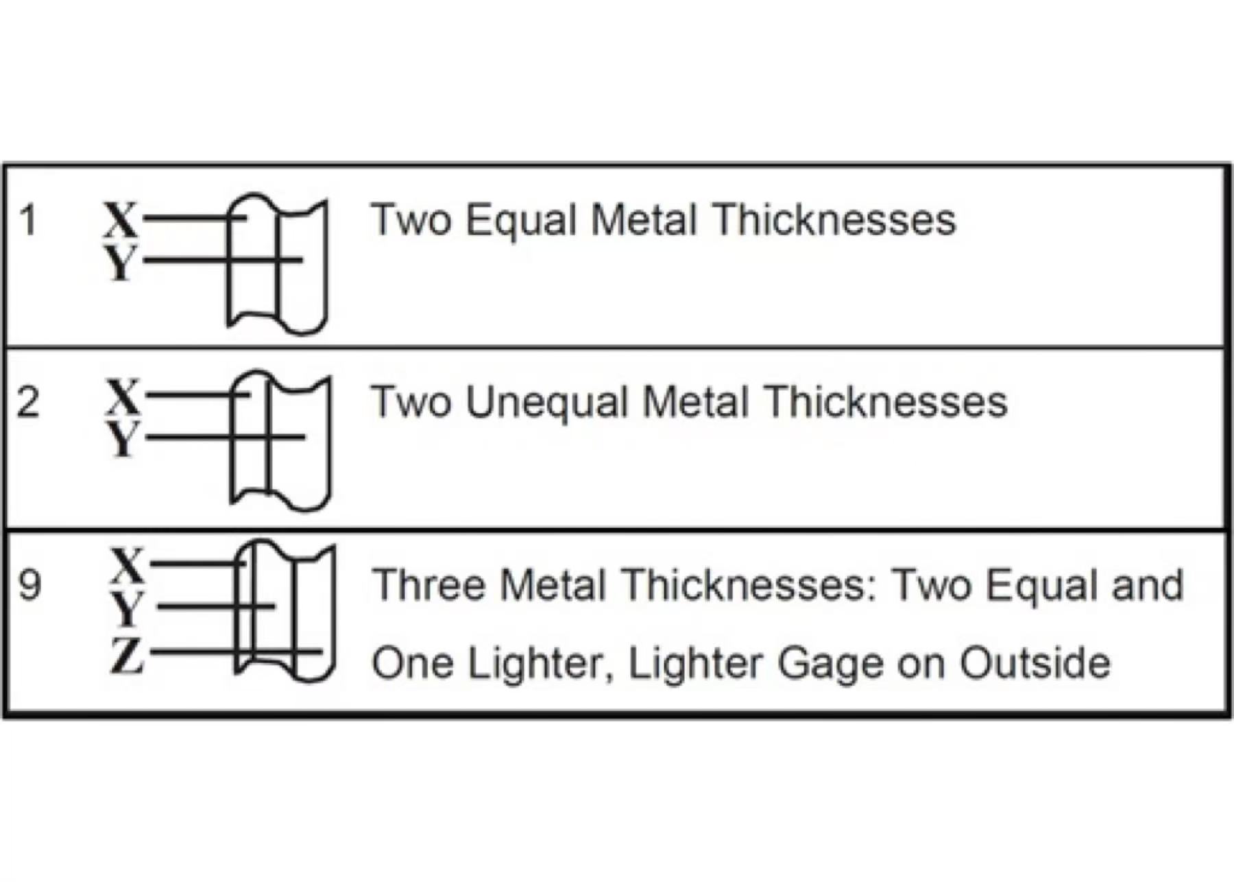
Taken together, the aforementioned documents allow for the creation of a robust design weld schedule under varying conditions. We will use the four (4) stack-ups noted above as our examples. The table below details the actual weld schedule for each combination, and includes some comments to better understand how the numbers were determined. Refer to Figure-2 for examples of the conditions. And as one might expect, there are some assumptions needed to complete this task:
- Dressed electrode caps used on both sides of the stack-up
- AC current used for all welds (the use of MFDC would result in a lower specified current value)
| Stack-Up | Material 1 | Material 2 | Material 3 | GMT
(Table 36 Condition) |
Weld Schedule
(lbf / cyc / kA) |
Comments |
| 1 | 0.89 mm HDG MILD CR3 | 0.89 mm HDG MILD CR3 | ~ | 0.89 mm HDG MILD CR3 (1) | 600 / 13 / 12.5 | Use Table 1
No schedule adjustment required for condition #1 |
| 2 | 0.89 mm HDG MILD CR3 | 1.40 mm HDG MILD CR3 | ~ | 0.89 mm HDG MILD CR3 (2) | 600 / 13 / 12.5 | Use Table 1
No schedule adjustment required for condition #2 |
| 3 | 0.89 mm HDG HSLA550 | 1.40 mm HDG MILD CR3 | ~ | 0.89 mm HDG HSLA550 (2) | 700 / 13 / 11.5 | Use Table 4
No schedule adjustment required for condition #2 |
| 4 | 0.89 mm HDG HSLA550 | 1.40 mm HDG MILD CR3 | 1.40 mm HDG HSLA550 | 1.40 mm HDG HSLA550 (9) | (1100 / 17 / 14.0)*
1210 / 17 / 15.4 |
Use Table 4
Schedule adjustment of 10% required for condition #9 |
*Initial schedule from chart, before the required modifications for force and current are applied
Summary
The results detailed above represent an industry-consensus approach to determining a robust welding condition for the stack-ups noted. This approach, utilized in the AWS C1.1, is based on the input of many industry professionals and has been validated with time. And as we alluded to earlier, the results are focused squarely on force, current and time.
There are, of course, other factors we have not addressed and one may encounter. These would include possible adjustments required due to the presence of sealers or adhesives, dealing with issues related to electrode polarity (MFDC only), and when the gauge ratios in the stack-up exceed the recommendations. These are where consulting someone with experience can be beneficial.
Figure-1: An example of a standardized weld schedule: The Milco sliding scale chart
Figure-2: Images representing conditions 1, 2 & 9 from AWS C1.1M/C1.1:2019, Table 36
References:
1) AWS C1.1M/C1.1:2019, Recommended Practices for Resistance Welding
Donald F. Maatz, Jr. is with Milco Manufacturing, and serves in the capacity of Senior Welding Engineer. He is past-chairman of the AWS-Detroit Section, serves on the D8 and D8.9 Automotive Welding Committees, is chair of the D8D, and an advisor to the C1 Resistance Welding Committee, is an AWS endorsed CWI and an instructor for the RWMA School. He is a graduate of Ohio State with a BS in Welding Engineering. This article would not have been possible were it not for the assistance from members of the Milco team. Send your comments/questions to Don at dmaatz@milcomfg.com.
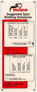
Figure-1: An example of a standardized weld schedule: The Milco sliding scale chart
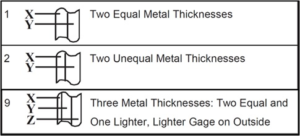
Figure-2: Images representing conditions 1, 2 & 9 from AWS C1.1M/C1.1:2019, Table 36