


Resistance Spot Welding (RSW) on galvanized coated steel parts can be challenging. One part of this challenge is the interaction between the material coating and the electrode caps. While it is acknowledged electrode caps are the most consumable portion of the RSW process, it still stands to reason one would want to extract the largest number of welds possible before they needed to be replaced.
There are many generic best practices one can do to help ensure you are obtaining the longest life possible from electrode caps. A partial list would include, but would not be limited to, ensuring the materials are weldable, the part presentation to the electrodes is good, the weld gun/tooling is capable, the electrode alignment and cooling are excellent, you have a weldable stack-up ratio, plus the actual weld schedule itself is suitable for the application. With all that being said, there is another process related item one can do to help ensure good welds are being made: Utilize a proper current stepper. To help understand what a current stepper can do for the RSW process, one must first understand what would occur if we were spot welding and did not have a current stepper boost feature on our weld control.
As each weld is made, the act of applying the scheduled weld time and secondary current, combined with the application of the needed weld force, physically degrades the condition of the electrode contact face. Some in the industry refer to this as mushrooming. This degradation may be subtle and barely noticeable even after many welds, or it may be dramatic, occurring very quickly in the production run. As an example, when the RSW process is used on cold-rolled bare steel and the parts are free of dirt and lightly coated with a known benign oil, it may be possible to make many thousands of welds before the electrode caps are no longer able to produce a weld of acceptable quality. On the other hand, I have seen some steels where the coating acts so aggressively as a wear agent by alloying with the electrode caps they were essentially ruined and required maintenance after less than a few dozen welds – In a word, wow! The most common electrode maintenance activity involves renewing the contact face geometry either by dressing the electrode cap, or replacing it.
What is a Current Stepper
The current stepper is a feature of the weld control and was created as a means to help increase the number of welds between electrode maintenance cycles. It accomplishes this by adjusting the secondary current in a programmed manner so that the current density (amps/unit area) remains relatively consistent as the electrode cap contact face area increases with every weld. The early weld controls only permitted for the addition of current at discrete intervals. This resulted in a plot of the current profile over the weld count looking like a set of steps, hence the name. A more modern weld control permits for a customized profile plot (e.g. boost of 1 amp/weld). However, despite the fact the profile for the modern example is a sloped line and no longer looks like set of stairs, the name has stuck.
There has been movement at the automotive OEM level away from utilizing the boost feature of current steppers and strictly using them as a counter to trigger a maintenance activity. This no-boost, dress early-dress often philosophy has merit in certain applications, and can be helpful in establishing a robust process. That being said, there are some unique aspects of welding on zinc coated material, especially hot-dipped galvanized (HDG), that may not work as well with this approach. I’ll elaborate more on this idea later in this article.
However, an important point before we move forward: This discussion is really relevant only for automotive grade coated steel products, specifically hot-dipped galvanized applications. I say this as other automotive grade coatings (electro-galvanized, galvanneal, etc.) do exhibit this behavior of concern, but typically to a lesser degree. Finally, the welding of any other material substrate (stainless, aluminum, etc.), or grade of galvanized coating (i.e. commercial, military, etc.) on steel, falls outside of the realm of this article’s applicability.
Also, please note for this discussion, and it bears repeating, all aspects of the RSW process need to be correct for the application being discussed. The important elements of material weldability, part presentation, weld gun capability, configuration and condition, electrode alignment, cooling, stack-up ratio, plus the actual weld schedule itself, must be suitable for the application. If this were not the case, we would not be able to correctly evaluate the application for electrode wear and weld performance over the course of a production run.
Actual Stepper Profile
So, how does one create a stepper (also called a current boost profile) for RSW? The first thing that must be done is to establish a robust starting point. This is really half the battle. From here you can utilize a generic stepper profile (see examples below) and see how it reacts. This will require some increased level of quality inspection on your part to make sure that you do not program a too aggressive or mild approach (e. g. expulsion or cold welds that appear over time). If either of these conditions develops, the profile will need to be changed to address it. The sample profile below is also broken down by electrode face type. This takes into account the different face growth characteristics with the different geometries. You will also need to consider the electrode wear for the application: Heavier gauge coated materials will wear the electrodes more aggressively, and may require either shorter weld counts, or higher boost values. The opposite is also true: Thinner gauge uncoated materials will wear the electrodes less aggressively, and may require either longer weld counts or lower boost values. Finally, there will always be a limit where, regardless of the boost profile, the electrode’s contact face is no longer able to support the weld and requires maintenance, either in the form of dressing or replacement.
Generic Stepper
| Step | 1 | 2 | 3 | 4 | 5 |
| Weld Count | 100 | 200 | 300 | 300 | 300 |
Amps/Weld B-Nose* | 2 | 1.5 | 1 | 1 | 1 |
Amps/Weld A/E-Nose* | 1 | 1 | 1.5 | 1.5 | 2 |
*See Reference-1 for electrode geometry information
Weld Acceptability Throughout a Production Run
It is not hard to conceptually grasp the idea of any welding process having a certain amount of variability – Things just inherently seem to change from moment to moment. For proof, one only needs to search for ‘slow motion welding video’ in YouTube. There you will find a myriad of choices, each seemingly better than the next, illustrating a world where metal ebbs & flows, seemingly of its own free will. Of course, these are all most likely visible-arc processes. Now search for ‘slow motion resistance welding video’. There will still be some visible-arc videos popping up, but now one can see some of the resistive processes. And when viewed through this slower and closer perspective, things look a bit different. With all of the aforementioned in mind, it makes sense one needs to verify the integrity of the weld throughout the entirety of the production run. This is where a stepper can help, and in the case to be illustrated, may be the most efficient way to accomplish the task.
The preceding paragraphs detailed a bit of how a RSW can change over time, and how a possible generic stepper profile can help. The one aspect of this degradation we will focus on is when the caps are initially installed and are making their very first welds. For clarity, we are talking about electrode caps either installed and used in their out-of-the-box condition (think a cold-formed face), or after they have been installed and dressed (think a cut face).
The First Few Welds
As mentioned above, it is very important to be aware of the weld integrity throughout the entirety of the production run. But if one is paying close attention to the first several welds on a coated material, you might find yourself in the following situation:
- When the electrode caps are installed and production starts on coated steels, you may be making almost unacceptably small welds. This can lead to a desire to increase the base schedule weld current and start with a higher initial value. However, we need to see what happens over just a short amount of time (think 30-100 welds) that makes this potentially a less than good idea.
- As our weld count grows, without making any changes to our initial the weld schedule, and not using a stepper of any kind, the welds that were initially small will start to grow. And eventually, if one is not careful, the welds will grow so large they might reach the point where expulsion becomes very possible.
- After a small number of welds (again, 30-100) we may find ourselves with a process that is now expelling metal and creating welds that are smaller than desirable – To the point they may be discrepant to the standard with respect to Minimum Weld Size (MWS).
Let’s more detail what is happening with the aforementioned scenario. For starters, when one is this early in the production run, each successive weld, each one, is different from the one made before it. This means weld #1 is not the same as weld #10, or weld #100. But what is changing? The contact resistance at the electrode sheet metal faying surface is changing.
To break this down a bit further. When we have brand new or freshly dressed caps there is a higher electrode contact resistance. This can be from the electrode face being a bit rough and/or the presence of oxides or other residual films. This can result in both a smaller contact area and a larger voltage drop across this interface than one would hope, or want to see. The end result is the potential with more heat where you don’t want it – at the electrode to sheet metal faying surface – and less heat available where you want it, at the faying surface of the materials to be welded.
But after 30-100 welds (give or take), the whole story changes. We now have the electrode making contact with a larger area, whatever oxides and/or films that were present have burnt away, and some zinc has been picked up and alloyed with the copper. All of these events lead to reduced weld-to-weld variability and the surface contact resistance being greatly reduced. We now have the heat going where we want it – at the faying surface of the materials to be welded. And more importantly, the effect of electrode face geometry becomes the dominant driving force for the weld size.
Another Point of View
The aforementioned scenario is a phenomenon seen frequently. One way to illustrate it is with a weld lobe. A weld lobe is one way to express the robustness of a particular resistance spot welding application (see Figure-1). In essence it is a means of graphically expressing the numerous combinations of weld currents and weld times that produce satisfactory welds for a specific set of conditions (weld force, electrode cap configuration, metal stack-up, etc.). The weld lobe (sometimes called a weld window) is created by plotting the values of weld current versus weld time that correspond to a particular measurable characteristic; most typically weld size. Note: The data from the evaluation at a specific weld time is called a weld range. If more than one weld time is tested for a specific condition (highly recommended) they are combined to form a weld lobe. See Reference-2 for more details on how to create a weld range. An important caveat to this process: Weld ranges are typically performed on electrodes that have been broken in – This process, dependent on how it is done, is called conditioning, or in some cases stabilization. We will use the term conditioning going forward.
- The left boundary of the lobe curve displays the combinations of weld current and weld time that produce a weld that meets the minimum acceptable quality requirements, in this case a 5.0 mm MWS. The combinations of weld current and weld time to the left of the curve may still produce welds but they will generally be of a less than the desired quality as measured against a particular characteristic.
- The right boundary of the lobe displays the combinations of weld current and time that correspond to substrate expulsion, or flashing. However, welds produced with parameters to the right of this curve may still meet engineering intent.
- The distance between these two boundaries at a given weld time is referred to as the current range. A wide current range is one indication of process robustness. As such, the stack-up in question would be tolerant to changes in the manufacturing process and welding equipment resulting from normal process variation and equipment degradation. Conversely, a narrow current range is indicative of a process that is far less tolerant of typical manufacturing process variations. Such processes are most likely ‘fussy’ and seem to demand much more than their fair share of attention.
We have helped to illustrate the effect of electrode conditioning by adding an additional data point in a weld lobe plot (See Figure-1). What is unique about this particular weld lobe plot is that it details the secondary current value when a new set of unconditioned electrodes produces a weld that meets the requirements of MWS. However, once the electrodes had been conditioned (see above), the secondary current required to achieve a weld at MWS (I-Min) was substantially lower. Additionally, the new unconditioned electrode MWS current is only slightly lower than the conditioned electrode expulsion current (I-Max). This is exactly the issue detailed above. And from a production standpoint, this represents a real problem as the electrodes are exhibiting a very dynamic break-in behavior due to variance with their contact face resistance.
A potential fallout from this dynamic behavior is the published results for a weld lobe might be of minimal value. There is one way around this: confirm the data by means of a Weld Lobe Point Verification. The Weld Lobe Point Verification test validates a specific set of welding parameters as to its ability to consistently produce welds of acceptable quality. The test is conducted by validating the weld point within the lobe. For typical automotive grade materials, the validation point is usually 500-1000 amps beneath the expulsion current for a given weld time and utilizes electrodes configured to mimic a production environment (i.e. out of the box without conditioning, or dressed). The welding portion of the validation consists of a series of peel coupons (typically 30 or more) at the desired validation point. All peeled test welds should be greater than MWS, and ideally exhibit no expulsion.
A Possible Alternative
One possible solution to this issue is to employ a negative stepper boost profile (See Figure-2). As detailed in the example, this type of boost profile permits the utilization of a higher initial starting secondary current with new electrode caps that quickly fades back to a baseline value more suitable for conditioned electrode caps. Once the electrode caps begin to exhibit normal wear, a positive value of boost can be programmed, thus prolonging the time between electrode maintenance cycles. While it will take a bit of experimentation, one should find the RSW process will be more robust and cost effective by employing this alternative boost strategy.
The RSW process can be very robust, even on coated materials. However, in order to achieve that robustness, there are many variables that must be considered, addressed if they are out of compliance, documented for reference, and finally maintained for the life cycle of the part. The current stepper needed is one of those.
Figure-1: A resistance spot weld lobe
Figure-2: A resistance spot weld current stepper boost profile for coated material
References:
1) RWMA Resistance Welding Manual, revised 4th Edition
2) AWS D8.9M-2022, Test Methods for Evaluating the Resistance Spot Welding Behavior of Automotive Sheet Steel Materials
Donald F. Maatz, Jr. is with Milco Manufacturing, and serves in the capacity of Senior Welding Engineer. He is past-chairman of the AWS-Detroit Section, serves on the D8 and D8.9 Automotive Welding Committees, is chair of the D8D, and an advisor to the C1 Resistance Welding Committee, is an AWS endorsed CWI and an instructor for the RWMA School. He is a graduate of Ohio State with a BS in Welding Engineering. This article would not have been possible were it not for the assistance from members of the Milco team. Send your comments/questions to Don at dmaatz@milcomfg.com.
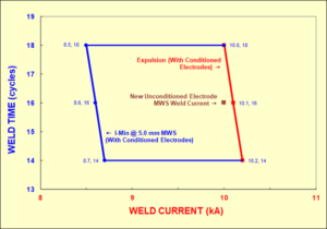
Figure-1: A resistance spot weld lobe showing weld size for new and conditioned electrodes
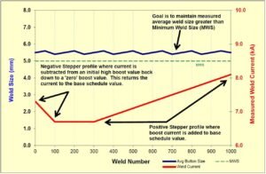
Figure-2: A resistance spot weld current stepper boost profile for coated material
View in Printable PDF Format